Size Range: 1/2” - 120” ( DN 15 - DN 3000)
Rating: 150, 300, 400, 600, 900, 1500, 2500;
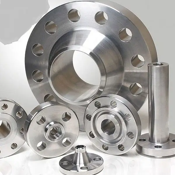
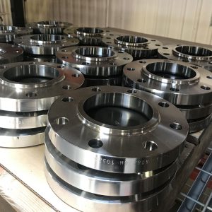
Type: Welding Neck, Long Welding neck, Slip on, Blind, Spectacle Blind,
Lap joint, Socket weld, Threaded, Orifice, Ring Joint Flange,
Spacer and Blank, Anchor Flange, API flange, etc.
Standard: ANSI B16.5, ANSI B16.47 Series A & Series B, AWWA C207, BS4504,
BS3293, DIN EN1092-1, API590, JIS/KS, ISO 7005-1, JB/T, etc.
Material: Carbon steel, Low Temperature Carbon Steel, High Yield Carbon Steel,
Plate Material, Low Alloy Steel, Stainless Steel, Duplex Stainless Steel.
C.S: A36, A105, A266 CL2/CL4, ST37.2, C22.8, S235JR, S355JR;
LTCS: A350 LF2 CL1/CL2/LF3;
HYCS: A694 F42/F52/F60/F62/F65/F70;
Plate: A515 Gr60/70, A516 Gr 60/70, A285 Gr A B C, A240 304, A240 316
LAS: A182 F5, F9, F11 CL1/CL2/CL3, F12 CL1/CL2, F22 CL1/CL3, F91
SS: A182 F304/L, F304H, F316/L, F317/L, F44
Duplex SS: A182 F51/UNS 31803, F53/UNS 32750
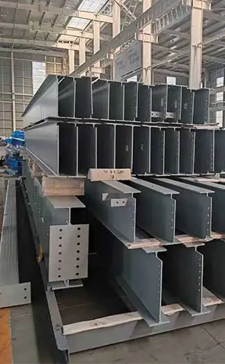
Application: Can be widely used in the field of Gas, Oil, Pipeline,Water Supply, Electricity and Machinery.
|
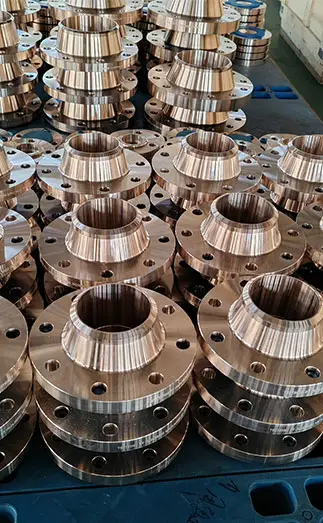
Welding Neck Flange
Weld Neck Flange features a neck extension and weld bevel. Provides a natural form connection ideal for larger, high-pressure applications.
|
|
Blind Flange
Blind Flange has no bore or inner diameter. They are often altered to include NPT threads or custom bore holes to function as hubless Slip On flanges.
|
|
Lap Joint Flange
Lap Joint Flanges are intended to saddle over a stub end fitting. They feature an extended hub and a machined radius at the base of the flat face.
|
|
Slip On Flange
Slip On Flange is designed to accept the pipe into the center/bore, allowing welding around the outer diameter of the pipe.
|
|
Socket Weld Flange
Socket Weld types have a socket to insert pipe when space limitations make Weld Neck flanges difficult to use.
|
|
Threaded Flange
Threaded Flanges contain a female NPT threaded center for connection to male threaded piping. These flanges are commonly implemented in reducing connections.
|


 English
 Español
 Français
 بالعربية